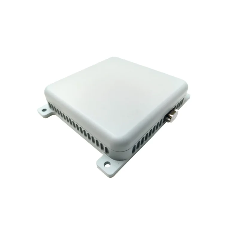
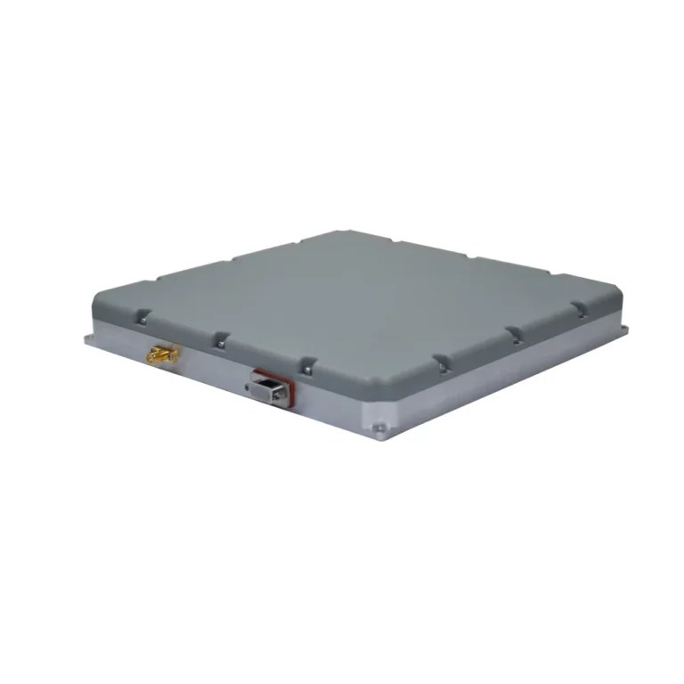
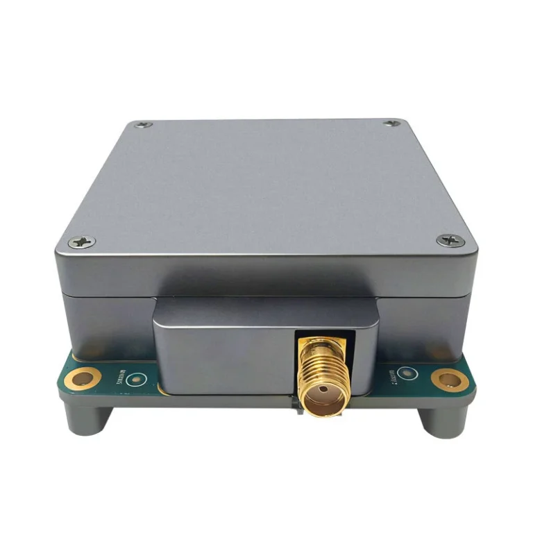
Anti-Jamming Antenna Selection for Small Fixed-Wing UAVs
I. Core Trade-off: Balancing Anti-Jamming Performance with SWaP
The primary challenge in selecting a Controlled Reception Pattern Antenna (CRPA) for small fixed-wing UAVs lies in the trade-off between anti-jamming capability and Size, Weight, and Power (SWaP). Unlike large UAVs with ample payload capacity, small platforms are highly sensitive to the antenna’s volume, weight, and mounting location, while often operating in complex electromagnetic environments.
Current mainstream solutions follow two technical paths: compact multi-element arrays and simplified anti-jamming units. The former uses multiple independent antenna elements to form a spatial array, capable of actively generating nulls in the radiation pattern. The latter achieves a degree of interference suppression through a high-gain single-element antenna combined with backend algorithms, representing a significant difference in both performance and integration complexity.
II. Compact Multi-Element Arrays: The Preferred Choice for High Performance
This solution typically employs a four-element antenna array. By distributing multiple independent elements within a limited planar area and utilizing backend digital signal processing to dynamically adjust the amplitude and phase weights of each element, the system forms a main beam towards the GNSS signal direction while adaptively generating nulls towards the direction of jammers. Theoretically, a four-element array can simultaneously nullify up to three strong jammers from different directions.
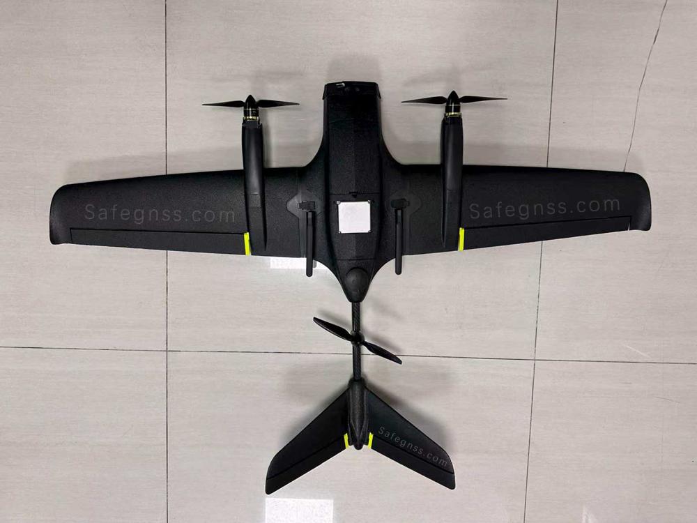
The image above shows a modified small fixed-wing drone equipped with Safegnss’s Small GNSS 4-Element CRPA Anti-Jamming Antenna Device (SGX-301).
From an engineering perspective, typical physical dimensions for such an antenna module are approximately 70 to 80 mm per side, with a thickness of less than 25 mm and an overall weight of around 180 to 200 grams. Power consumption is generally below 6 watts, allowing it to be powered by the UAV’s main flight battery or a separate power module. It is critically important that such antennas be mounted at the highest point on the airframe with a clear, unobstructed view of the sky, free from electromagnetic shielding (e.g., the upper fuselage surface away from the vertical stabilizer and engine). Carbon fiber skins, metal components, or large electronic equipment can severely degrade the antenna’s radiation pattern, drastically compromising its anti-jamming performance.
Installation also requires careful attention to shielding and isolation. The RF cable connecting the antenna to the receiver must be a high-quality, double-shielded coaxial type, routed as far as possible from high-interference sources like electronic speed controllers (ESCs) and video transmitters. Adding a common-mode choke or filter to the power supply is recommended to suppress power ripple that could interfere with the antenna’s integrated low-noise amplifiers (LNAs).
The compact four-element array solution is suitable for medium-to-high-end missions with a defined requirement for anti-jamming capability, such as surveying or reconnaissance near urban fringes, high-voltage transmission corridors, or areas with suspected illicit signal emitters. Its adoption comes at the cost of significantly increased onboard weight and installation complexity, imposing higher demands on the CG balancing and aerodynamic design of small UAVs.
III. Simplified Anti-Jamming Units: A Lightweight Compromise
For smaller UAVs with extremely tight weight budgets or payload capacity, a single-element anti-jamming antenna can be considered. These products are essentially high-gain active antennas working in concert with backend interference detection algorithms. They lack spatial nulling capability but achieve limited jamming mitigation by improving the signal-to-noise ratio (SNR) and filtering out some broadband noise.
Such antenna modules can typically be packaged within dimensions of 70 mm × 60 mm × 25 mm or less, weigh as little as 110 grams, and commonly consume under 7 watts of power. Due to their simple construction, they often feature plug-and-play interfaces, requiring no complex array calibration or configuration, thus presenting a lower technical barrier for operators.
However, it is crucial to understand their performance boundaries: they are primarily designed to counter occasional, non-cooperative narrowband or wideband interference common in everyday electromagnetic environments, such as nearby walkie-talkie transmissions or poor-quality power supply radiation. Their protective capability is significantly inferior to multi-element arrays when facing strong, simultaneous jammers from multiple directions or deliberate barrage jamming targeting GNSS bands. Consequently, this solution is best suited for operations in electromagnetically quiet environments, such as rural areas, agricultural fields, or over water, or for budget-sensitive, training, or recreational flights where the primary goal is not mission-critical reliability.
IV. Key Integration Considerations
Regardless of the chosen solution, the following four engineering factors require careful verification:
Weight and Center of Gravity (CG) Impact: The weight of the antenna module contributes to the total airframe weight, and its mounting location directly affects the CG. It is advisable to mount the antenna as close as possible to the aircraft’s pitch and roll axes to avoid creating excessive moments if placed on the tail or wingtips.
Mounting Location and Obscuration Avoidance: The antenna must have an unobstructed view of the upper hemisphere. The optimal mounting location for a fixed-wing UAV is typically the forward upper fuselage. If the airframe is constructed of carbon fiber, a window or cutout with an overlay of fiberglass or other RF-transparent material must be created beneath the antenna’s footprint, as the conductivity of carbon fiber can cause several decibels of attenuation in the antenna pattern.
Power Supply Purity: Active antennas are sensitive to power supply noise. It is strongly recommended to draw power from a regulated output on the flight controller or a dedicated power module. Ferrite beads or small common-mode chokes should be placed near the antenna’s power input. Avoid sharing the same power branch with inductive loads such as servos or gimbal motors.
Cable Routing and Shielding: The antenna’s RF cable should be kept as short as possible and must be double-shielded coax. The cable route should follow structural members like the fuselage longeron, staying well clear of ESC power wires and video transmitter antennas. Wrapping the cable in copper foil or adding a ferrite ring can provide additional isolation if necessary.
V. Decision Logic for Selection
For practical selection, the following logic is recommended:
- Determine Requirement Criticality: Ascertain whether anti-jamming capability is a hard requirement or a nice-to-have. If operating in environments known or suspected to contain jammers for critical tasks, select a compact multi-element array. If flying primarily in electromagnetically clean areas with limited budgets, a simplified unit is sufficient.
- Check Available Payload Capacity: If the maximum effective payload is less than 300 grams, only a simplified solution or an ultra-lightweight four-element array is feasible. If ample payload capacity exists and reliability is paramount, prioritize anti-jamming performance.
- Assess Installation Feasibility: Verify the existence of a flat, unobstructed mounting surface on the airframe of sufficient size, and whether RF cables can be routed without compromising structural integrity.
- Consider System Integration Level: Some antennas integrate the array and processing unit, outputting a digital IF signal directly—this is the most user-friendly option. Others use a separate architecture with a discrete backend processing unit. While potentially offering higher performance, such systems require matching and tuning by the integrator and are best suited for teams with RF engineering expertise.
In summary, for the vast majority of medium-to-high-end applications on small fixed-wing UAVs, the compact four-element array antenna represents the optimal balance, providing true spatial anti-jamming capability at a reasonable weight penalty. One should only consider the simplified single-element anti-jamming unit if the UAV has a takeoff weight below 2 kg, the budget is extremely constrained, or the operational environment is confirmed to be free of strong jammers. Final selection should be validated through flight testing, ideally preceded by ground-based range tests and jammer simulation to characterize performance prior to flight.