Abstract
As Global Navigation Satellite Systems (GNSS) are increasingly deployed in civilian domains such as autonomous driving, aviation, maritime operations, power infrastructure, and precision agriculture, the vulnerability of GNSS signals to both intentional and unintentional interference has become a critical issue. The 4‑element Controlled Reception Pattern Antenna (CRPA), as a core spatial‑domain anti‑jamming solution, uses an antenna array and adaptive beamforming algorithms to dynamically create nulls in the direction of interference. This paper systematically examines the technical principles, key characteristics, general performance parameters, and typical application scenarios of 4‑element CRPA systems. The objective is to provide a technical reference for engineering selection and deployment.

Keywords: CRPA; anti‑jamming antenna; GNSS; nulling; beamforming
1. Introduction
In modern information‑intensive societies, GPS and other GNSS have become indispensable spatiotemporal references for intelligent transport systems, drone logistics, power grid synchronisation, and precision agriculture. However, satellite signals travel approximately 20 000 km to reach the ground and arrive extremely weak – typically between –160 dBm and –130 dBm, about 30 dB below the ambient noise floor. This inherent weakness makes them highly susceptible to interference from relatively low‑power transmitters. With the proliferation of software‑defined radio (SDR) technology, the barrier to acquiring or building GNSS jammers has dropped significantly, posing a growing threat to GNSS integrity.
Three main approaches exist to counter GNSS interference. The first enhances receiver front‑end filtering and tracking algorithms, but it has limited effectiveness against wideband noise jamming. The second uses INS/GNSS integration, which can maintain position during brief signal loss but does not prevent the loss itself. The third employs antenna‑array spatial processing – CRPA technology. Among CRPA configurations, the 4‑element design offers the best balance among performance, physical size, and cost, and is therefore the most widely deployed form. This paper focuses on the technical characteristics, generic performance metrics, and practical use cases of 4‑element CRPA.
2. Technical Characteristics
2.1 Basic Principle: Spatial Filtering
A conventional Fixed Reception Pattern Antenna (FRPA) has a static radiation pattern. It passively receives signals from the upper hemisphere and cannot distinguish between legitimate satellite signals and interference. In contrast, a 4‑element CRPA uses four independent antenna elements. The phase and amplitude differences among the elements encode direction‑of‑arrival (DoA) information for all incident signals.
An adaptive beamforming algorithm computes a complex weight for each element. The array then steers gain towards the satellite directions while creating cancellation nulls in the directions of interference sources. This process acts as a spatial filter that physically suppresses interference before the signal reaches the receiver, without requiring any modification to the back‑end GNSS receiver hardware.
2.2 Element Design: Quad‑Feed and Broadband Coverage
The performance of a 4‑element CRPA ultimately depends on the quality of its individual antenna elements. Modern designs widely adopt quad‑feed (four‑point orthogonal feed) to achieve right‑hand circular polarisation (RHCP). Compared with older “quadrature hybrid” approaches, quad‑feed maintains stable polarisation purity over a broader beam angle, reducing signal degradation when the host platform changes its attitude.
Frequency coverage must be wide enough to accommodate GPS L1/L2, BeiDou B1/B2/B3, Galileo E1/E5a/E5b, GLONASS G1/G2, and other bands. Wideband coverage not only improves system compatibility but also allows the antenna to handle interference distributed across the L‑band. Some high‑end models include headroom for future navigation bands, ensuring continued effectiveness for protected spectrum allocations.
2.3 Nulling Capability: Number and Depth of Nulls
The two most critical performance metrics for a 4‑element CRPA are the number of simultaneous nulls and their depth (attenuation). With four spatial degrees of freedom, the theoretical maximum number of independent nulls is three (one degree remains to maintain satellite signal gain). In practice, mainstream 4‑element CRPA systems support 2 to 3 simultaneous nulls and achieve broadband jamming suppression greater than 40 dB. Dual‑band designs can allocate nulls separately on the L1 and L2/L5 bands, raising the total number of jammers that can be countered to 4–6 (1–3 per band), with null depths typically in the 20–40 dB range.
Null depth directly translates to field performance. A 40 dB suppression ratio means the interference power is reduced to one ten‑thousandth of its original value. This is sufficient against medium‑power jammers (1–10 W) located a few hundred metres to a few kilometres from the receiver. It is worth noting that deeper nulls are not always better – excessively deep nulls can raise side‑lobe levels and introduce additional noise. Practical designs trade off anti‑jamming performance against the final signal‑to‑noise ratio.
2.4 Integration Architecture: Embedded Receiver vs. Separate Antenna
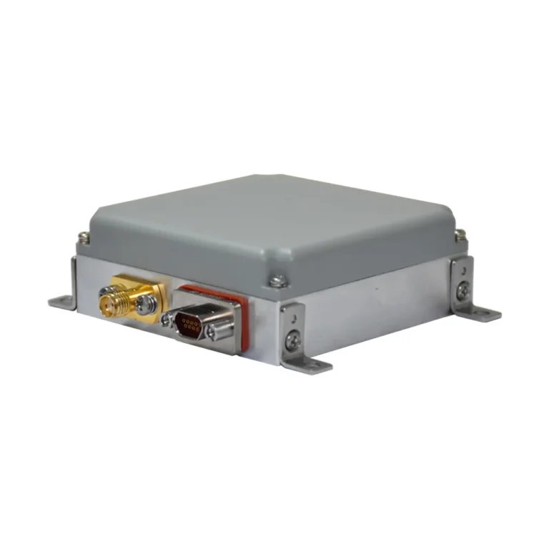
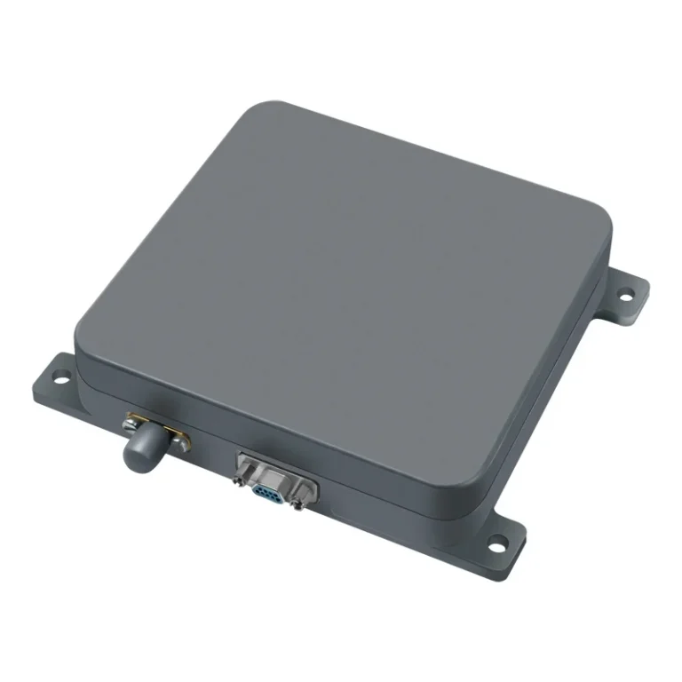
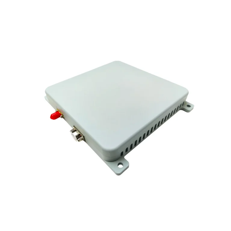
Commercially available 4‑element CRPA products fall into two architecture categories. The first is a passive/antenna‑only array, which requires an external control unit to perform the anti‑jamming processing. The second is an integrated system that combines the antenna array, RF front‑end, beamforming processor, and GNSS receiver in a single enclosure, outputting anti‑jammed PVT (position, velocity, time) data directly.
The integrated approach is compact and plug‑and‑play, making it suitable for space‑constrained platforms such as small UAVs. The separate‑components approach offers greater flexibility: the user can select a control unit matched to the expected threat level, or keep their preferred back‑end receiver. In addition, some 4‑element CRPA systems provide a serial data interface that outputs interference‑detection status, affected bands, and approximate direction‑of‑arrival of jammers. This situational awareness can be valuable for diagnosing electromagnetic environments.
2.5 SWaP Constraints: Balancing Size, Weight and Power
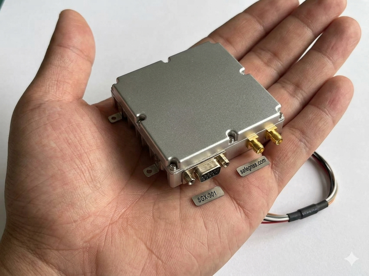
Size, weight and power (SWaP) are the main constraints limiting where CRPA can be deployed. Early anti‑jamming systems were bulky, heavy and often consumed tens of watts, making them impractical for small UAVs or portable devices. New‑generation 4‑element CRPA designs have dramatically improved SWaP. Typical products now measure about 110×100×27 mm and weigh as little as 460 g. Ultra‑light designs can be as small as 72×72×23 mm and weigh under 200 g.
Power consumption has also fallen. Some 4‑element systems draw as little as 140 mA at 5 V (≈0.7 W), while fully integrated units with internal receivers typically stay below 18 W. Low power consumption allows battery‑powered platforms to operate for extended periods, greatly expanding the range of feasible applications.
3. General Performance Metrics
This section summarises industry‑wide performance parameters for 4‑element CRPA systems, without referring to any specific product or manufacturer.
3.1 Anti‑Jamming Metrics
- Number of nulls: Maximum number of independent directions in which the array can suppress interference. The theoretical upper bound for a 4‑element array is 3. Actual products support 2 or 3 simultaneous nulls. Dual‑band designs can produce nulls on each band independently, yielding 2–6 nulls in total.
- Jamming suppression ratio (null depth): Typically 30–40 dB for commercial and industrial products. High‑end systems with multi‑stage filtering can achieve 60–80 dB.
- Response time: Time from interference onset to effective null formation. Modern adaptive algorithms achieve response times below 10 ms, which is sufficient against pulsed or frequency‑hopping jammers.
3.2 RF and Antenna Metrics
- Operating bands: Most products cover at least GPS L1 (1575.42 MHz) and L2 (1227.60 MHz), as well as BeiDou B1 (1561.098 MHz) and Galileo E1 (1575.42 MHz). Full‑band models also include L5 (1176.45 MHz), E5 etc.
- Gain and axial ratio: Element peak gain is typically 2–5 dBi. The array beam coverage should be reasonably uniform over the upper hemisphere (elevation 0°–90°). Axial ratio (right‑hand circular polarisation) is better than 3 dB at boresight and better than 6 dB at the edge.
- VSWR: Typically <2.0:1 (often <1.5:1), indicating good matching.
3.3 Environmental and Reliability Metrics
- Operating temperature: Industrial‑grade products are usually rated –40°C to +85°C.
- Ingress protection (IP): Outdoor installations require IP67 (dust‑tight and protected against temporary immersion) or higher. For harsh maritime or industrial environments, IP69K (protection against high‑pressure, high‑temperature water jets) is available.
- Vibration and shock: 4‑element CRPA systems are designed to withstand typical transport and operational vibration and mechanical shock per IEC 60068 or equivalent standards.
- EMC: Products must comply with regional or industry EMC regulations – not emitting harmful interference and maintaining a specified immunity to external fields.
3.4 Interfaces and Outputs
- RF connectors: Standard types such as SMA, TNC or N, carrying either the post‑processing anti‑jammed signal or the raw array signals.
- Control and data interfaces: Integrated systems typically provide RS‑232, RS‑422, Ethernet or USB for outputting positioning data and receiving configuration commands. Separate systems use dedicated interfaces between the antenna and the control unit.
- Auxiliary information: Some CRPA systems output NMEA‑like messages that include jammer detection flags, affected frequency bands, and approximate jammer direction. This data can be used for situational awareness and fault diagnosis.
4. Typical Application Scenarios
4.1 Drones and Low‑Altitude Aircraft
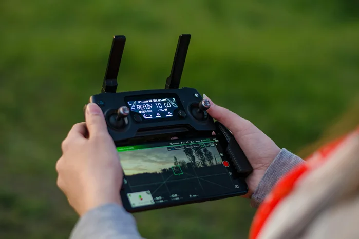
The drone industry has grown rapidly across logistics, agriculture, power line inspection, and cinematography. Most drones use low‑cost GNSS receivers with very limited anti‑jamming capability. In urban environments, out‑of‑band emissions from telecom base stations, broadcast towers and Wi‑Fi devices can cause front‑end blocking. Near airports or above critical infrastructure, deliberate jamming may be encountered.
For these platforms, a 4‑element CRPA provides basic anti‑jamming protection while allowing flight to continue. Lightweight designs (under 500 g) can be integrated into drones with take‑off weights of 2–5 kg. A suppression ratio of 40 dB is sufficient against common low‑ to medium‑power jammers. Integrated CRPA systems output anti‑jammed PVT directly, requiring minimal modification to the flight controller. For small UAVs, low power consumption (<3–5 W) is essential, and a low‑profile antenna shape reduces drag and centre‑of‑gravity shift.
4.2 Intelligent Transport and Autonomous Driving
Higher‑level autonomous driving (L4/L5) demands extremely high positioning reliability. INS/GNSS integrated systems provide centimetre‑level accuracy in open areas, but they remain vulnerable – not only to tunnels and overpasses (signal blockage) but also to RF interference. Although autonomous driving systems typically fuse lidar, vision and radar, GNSS remains an important redundant positioning source during adverse weather or sensor degradation.
Key applications for 4‑element CRPA in transport include:
- High‑definition mapping vehicles: These vehicles must collect data in diverse urban environments. CRPA reduces data interruptions and precision loss caused by interference.
- RoboTaxis and autonomous buses: Their operating routes may pass through electromagnetically complex areas (e.g., commercial districts, transport hubs). CRPA provides an extra layer of positioning reliability.
- Roadside units (RSUs) for V2X: RSUs need continuous, reliable timing and positioning. Their roadside locations often aggregate electromagnetic interference. CRPA improves operational stability.
Current production passenger cars are not yet equipped with CRPA due to cost and installation space constraints. As functional safety standards (e.g., ISO 26262) raise the integrity requirements for positioning systems and as volumes increase, basic anti‑jamming antennas may begin to appear in premium vehicles by 2030.
4.3 Railway and Rail Transit
Railways are increasingly reliant on GNSS. Train positioning and control systems (CTCS in China, ETCS in Europe) are exploring GNSS to supplement or replace track circuits and balises for more efficient moving‑block operations. However, railway environments are electromagnetically challenging: arcing from electrification catenaries generates broadband RF noise; tunnels and mountainous terrain cause multipath and attenuation; and unauthorised signal blockers (used in some depots or stations) pose deliberate threats.
A 4‑element CRPA mounted on the locomotive roof can:
- Improve availability in electrified sections by suppressing broadband noise from catenary arcing.
- Increase tolerance to intentional blockers used in some stations, preventing complete loss of positioning.
- Support high‑precision timing for railway communications and signalling systems, where time‑synchronisation requirements are stringent.
Railway installations require high vibration tolerance, wide temperature operation and long‑term reliability. CRPA products intended for rail must meet industry standards such as EN 50155.
4.4 Maritime and Port Operations
The maritime environment has distinctive electromagnetic characteristics. Large vessels carry multiple communication systems (satellite terminals, VHF radios, radar) that may operate in bands adjacent to GNSS, causing out‑of‑band interference or front‑end saturation. Port areas contain many industrial and wireless devices, creating a complex EM environment. For vessels using GNSS for dynamic positioning (DP), and for automated container terminals with AGVs and gantry cranes, signal loss can create safety risks or stop operations.
Advantages of 4‑element CRPA in maritime applications:
- Adjacent‑band interference rejection from satellite communication terminals and radar, enabled by wideband design and advanced filtering.
- Multipath mitigation: Sea surface reflections are a common source of multipath. CRPA beamforming can suppress low‑elevation multipath signals.
- Environmental robustness: IP67 or higher CRPA models withstand salt spray, wave impact and high‑pressure water jets, meeting the requirements of marine equipment.
4.5 Critical Infrastructure Timing and Synchronisation
Power grids, telecom networks, data centres and financial trading systems increasingly rely on GNSS timing. These systems typically use single‑frequency (L1) GNSS timing receivers, which are highly susceptible to low‑cost jammers – even low‑power devices sold in open markets can disrupt timing over hundreds of metres. For national‑level time synchronisation networks, a single loss of lock can create a cascade: loss of synchronisation in PMUs (phasor measurement units) may trigger false grid protection operations; drift in telecom base‑station clocks can cause handover failures; inaccurate financial timestamps may lead to legal disputes.
In these fixed‑site scenarios, a 4‑element CRPA provides defence in depth. Unlike mobile platforms, fixed installations are not SWaP‑constrained, so higher‑performance control units and larger arrays can be used. A CRPA combined with an OCXO or atomic clock can maintain microsecond‑ or even sub‑microsecond timing accuracy while under interference, meeting the stringent requirements of power‑system synchronisation.
Recommendation for timing applications: Pay attention to the signal‑processing delay of the CRPA system and its stability. Some adaptive algorithms introduce variable delay, which degrades timing accuracy. Select a CRPA that supports “delay calibration” or a “fixed‑delay mode” and pair it with a stable local oscillator for holdover.
4.6 Precision Agriculture and Mining
Precision agriculture and open‑pit mining are major users of high‑accuracy GNSS. Autonomous tractors in agriculture and unmanned haul trucks in mining require centimetre‑level real‑time positioning. These sites are characterised by open sky and good satellite visibility – but that same openness means no natural shielding (buildings, terrain) when interference does occur.

In agriculture, interference can come from wireless devices on the farm (drone controllers, irrigation control systems), nearby industrial equipment, or deliberate sabotage. In mining, two‑way radios on large trucks and ignition systems on heavy equipment can produce strong emissions. Although not intentional jamming, their power and spectral content can disrupt GNSS receivers.
A 4‑element CRPA significantly improves system availability in these settings. When interference appears, the CRPA automatically forms nulls, allowing operations to continue without operator intervention. For 24/7 mining operations or time‑sensitive planting/harvesting, this seamless anti‑jamming capability translates directly into productivity gains and prevention of downtime.
4.7 Surveying and Structural Monitoring
High‑precision surveying, geohazard monitoring (landslides, dam deformation), and structural health monitoring of bridges and high‑rise buildings require higher continuity and reliability than dynamic positioning. These applications typically use long‑duration static observations with post‑processing or real‑time differential corrections to achieve millimetre‑level accuracy. If interference occurs during an observation session, the entire dataset may be corrupted, wasting time and incurring repeat field costs.
In this context, the value of a 4‑element CRPA lies in data integrity assurance. On sites with intermittent interference (e.g., urban environments, near high‑voltage power lines, next to telecom towers), a conventional antenna may collect contaminated data. A CRPA suppresses the interference in real time and outputs a clean signal. For remote automated monitoring stations (e.g., landslide monitoring points), the CRPA can also provide interference alarms, helping operators distinguish between equipment failure and external interference.
Recommendation for surveying applications: Survey‑grade positioning requires very stable antenna phase centres. When selecting a 4‑element CRPA, verify that the phase‑centre variation meets sub‑millimetre accuracy. Some CRPA designs exhibit phase‑centre movement when nulls are steered. Either the unit must be calibrated for each steering direction or a phase‑centre‑stabilised model should be chosen.
5. Technical Challenges and Trends
5.1 Current Challenges
Cost remains the primary barrier. A complete 4‑element CRPA system costs between several thousand and tens of thousands of RMB, whereas a standard GNSS antenna costs tens to a few hundred RMB. For price‑sensitive consumer drones or mass‑market autonomous vehicles, this gap is unacceptable. Future cost reduction will require chip‑level integration, silicon process optimisation, and higher production volumes.
Trade‑off between complexity and reliability. CRPA adds electronics and processing, which increases the probability of system failure. For high‑reliability applications (aviation, rail, power), the CRPA must be subjected to rigorous failure mode analysis (FMEA) to ensure that its failure does not compromise the original navigation function.
Timing accuracy. The adaptive signal processing inside a CRPA, particularly the variable group delay introduced by the null‑forming filters, degrades timing accuracy. For applications that are purely timing‑oriented (e.g., telecom base stations), a filtered FRPA rather than a full CRPA may be the better choice – or a CRPA model that supports delay calibration.
Lack of standardisation and certification. Most CRPA products are proprietary designs, with no common performance test standard or interface specification. In regulated industries (rail, civil aviation, power), products must undergo lengthy approval processes, which slows the adoption of new CRPA technology.
5.2 Future Trends
CRPA technology is evolving in the following directions:
- Adaptive algorithm advances: Using deep reinforcement learning and other AI methods to optimise beamforming, improving response time and suppression effectiveness against new interference types (pulsed, frequency‑hopping).
- Multi‑sensor fusion: Tight integration of CRPA with IMUs, cameras or lidar, so that short‑term positioning remains available even when GNSS is completely lost.
- Software‑defined CRPA: Using reconfigurable RF front‑ends and firmware updates to adapt to new interference types, new bands, and new constellations, extending the useful life of the hardware.
- Chip‑scale integration: Integrating RF front‑end, beamformer and GNSS baseband on a single chip to dramatically reduce cost and power, eventually bringing CRPA into consumer markets.
- Delay‑calibration techniques: For timing applications, developing CRPA architectures whose signal‑processing delay can be precisely calibrated or locked, meeting critical‑infrastructure timing requirements.
6. Selection Recommendations and Conclusions
6.1 Key Selection Criteria
When selecting a 4‑element CRPA system, the following factors should be considered:
- Characterise the interference environment: Identify the types (wideband/narrowband, continuous/pulsed) and expected number of simultaneous interference sources. For benign environments, a basic system (30–40 dB suppression, 2 nulls) may suffice. For stronger or more complex threats, a dual‑band, multi‑null model is justified.
- Evaluate platform SWaP constraints: For small UAVs or handheld devices, prioritise lightweight, low‑power integrated systems. For fixed sites or large vehicles, use higher‑performance separate‑component systems.
- Check interfaces and data needs: Ensure the output format (PVT, raw array signals, or IF samples) is compatible with the back‑end equipment. Determine whether interference‑situational awareness (jammer direction, band) is required, and whether timing outputs (PPS, IRIG‑B) are needed.
- Verify environmental ratings: Confirm that operating temperature, ingress protection, vibration and shock ratings meet the actual deployment environment. IP67 is recommended as a minimum for outdoor or industrial installations.
- Certification and compliance: For regulated industries (rail, civil aviation, power), check whether the product has passed the relevant certifications (e.g., EN 50155, TSO, IEC 61850) or meets the required standards.
6.2 Conclusions
The 4‑element CRPA, through dynamic spatial nulling, fundamentally changes the passive reception paradigm of conventional GNSS antennas. It is proving its value across a wide range of civilian and industrial applications: drone logistics, autonomous driving, railway signalling, port automation, power grid synchronisation, geohazard monitoring, and more. Different 4‑element products trade off SWaP, nulling depth, band support, and situational awareness differently; users must select a solution that matches their specific threat environment, platform constraints, and industry requirements.
As technology matures and costs decline, CRPA is moving from niche professional domains into broader markets, offering more secure and reliable GNSS services to a society increasingly dependent on spatiotemporal information. For engineering decision‑makers, evaluating and introducing CRPA in critical applications is no longer a question of “whether” but of “when and how”.
References
[1] TE Connectivity. CRPA 4 Element and 7 Element Brochures. 2017.
[2] TUALCOM. *TUALAJ 4100 GPS/GNSS Anti‑Jam CRPA System Data Sheet*.
[3] Calian. *CR8894PXF+ Anti‑Jam Four Element Controlled Reception Pattern Antenna (CRPA) Datasheet*.
[4] Tallysman (Calian). *CR8894SXF+ GPS Antenna Built for Military and Maritime Infrastructure Applications*. 2025.
[5] Chelton (Cobham Antenna Systems). *Type 20‑7009 Four Element CRPA Antenna, GPS L1/L2 Bands (P and M Code)*.
[6] ST Engineering. GNSS Anti‑Jam Antenna Product Brief.